> ## Documentation Index
> Fetch the complete documentation index at: https://docs.researchanddesire.com/llms.txt
> Use this file to discover all available pages before exploring further.
# Board Design and Wiring
> Wiring diagrams and GPIO pinouts for the official OSSM PCB and alternative configurations
This guide shows you how to connect the official OSSM PCB and how to wire alternative configurations using an ESP32, level shifting, and common motor drivers.
## Prerequisites
Before you begin, make sure you have:
* An ESP32 development board (ESP32‑DevKitC or compatible)
* A motor driver that accepts step/direction inputs
* A power supply sized for your motor and driver
* Basic tools: wire strippers, small screwdriver set, multimeter
Most ESP32 boards use 3.3V logic. At higher speeds this can cause missed steps with 5V‑logic drivers. Use a level shifter to convert step/direction/enable to 5V for reliable operation.
### Prototyping components (for custom wiring)
If you are wiring without the official PCB, you will typically need:
* Logic level shifter (3.3V → 5V, 4+ channels)
* Solderless breadboard or proto board
* Dupont jumpers (male↔male and male↔female)
* 5V rail for the high‑side of the level shifter (often available from your driver or a separate regulator)
Keep signal wiring short and tidy. Route step/direction/enable away from motor and power leads to minimize noise.
## Official OSSM wiring
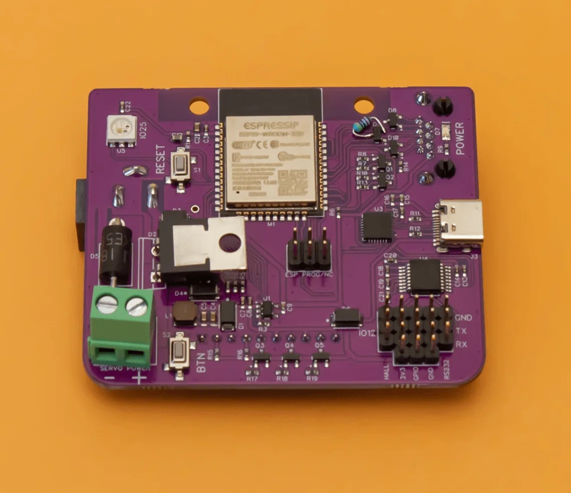
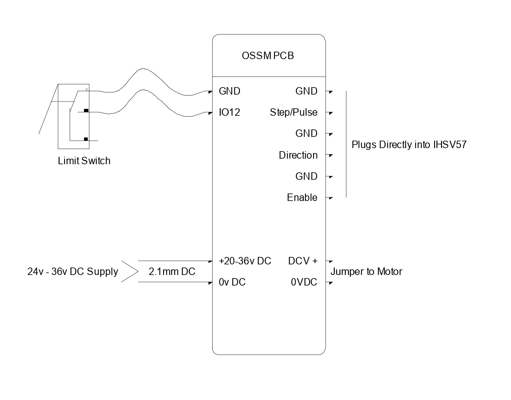
The reference OSSM PCB includes level shifting and standardized headers. This is the recommended approach for most builds.
### Reference board layout
 ### PCB connection diagram
 ### ESP32 GPIO pinout (default)
These are the default firmware mappings for the OSSM PCB:
| Signal | GPIO Pin | Function |
| --------- | -------- | ----------------------------------------- |
| Step | GPIO 14 | Step pulse output to motor driver |
| Direction | GPIO 27 | Direction signal to motor driver |
| Enable | GPIO 26 | Enable/disable motor driver |
| Encoder A | GPIO 36 | Quadrature encoder channel A (input‑only) |
| Encoder B | GPIO 39 | Quadrature encoder channel B (input‑only) |
### ESP32 GPIO pinout (default)
These are the default firmware mappings for the OSSM PCB:
| Signal | GPIO Pin | Function |
| --------- | -------- | ----------------------------------------- |
| Step | GPIO 14 | Step pulse output to motor driver |
| Direction | GPIO 27 | Direction signal to motor driver |
| Enable | GPIO 26 | Enable/disable motor driver |
| Encoder A | GPIO 36 | Quadrature encoder channel A (input‑only) |
| Encoder B | GPIO 39 | Quadrature encoder channel B (input‑only) |
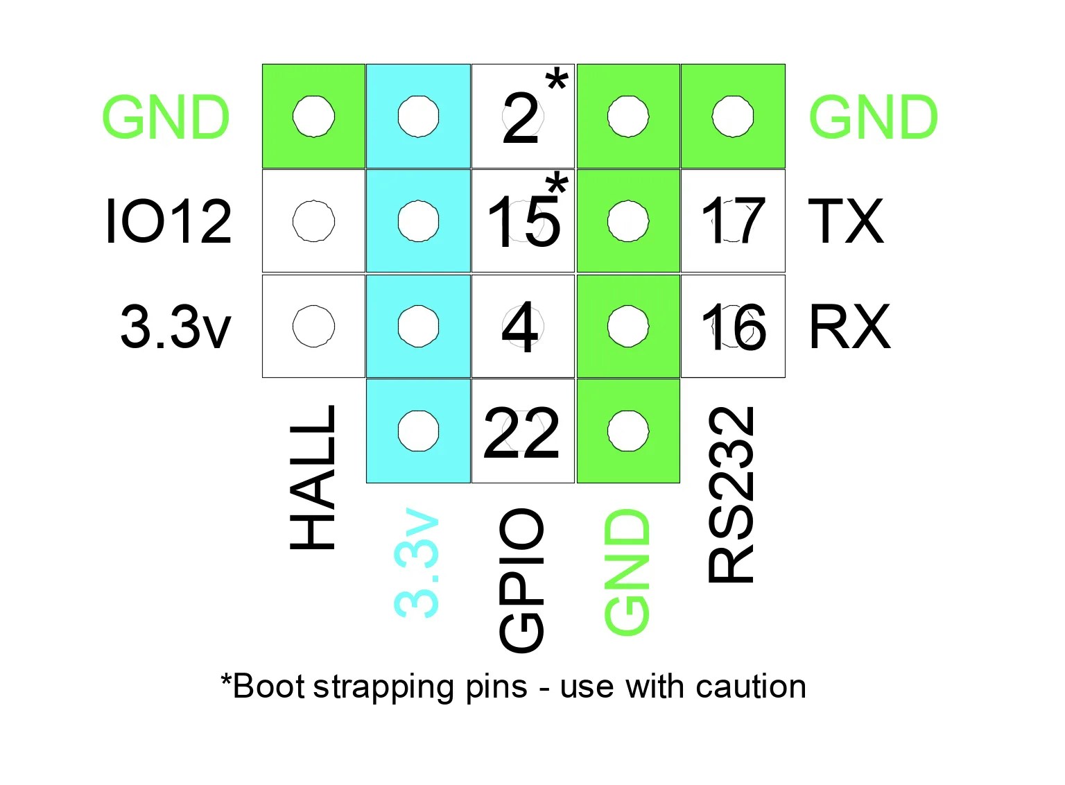
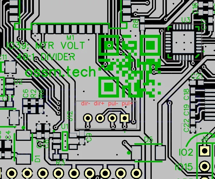 Firmware can remap pins if needed. If you change wiring, update your firmware configuration to match.
## Alternative wiring configurations
The following setups are community‑tested patterns. Your hardware may require different pin assignments or minor wiring changes. Always consult your driver and motor datasheets.
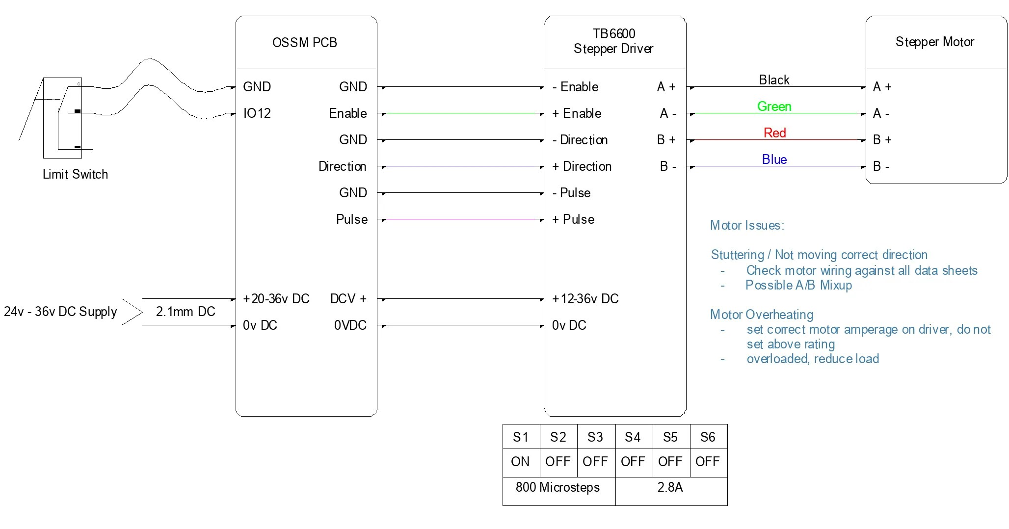
### TB6600 stepper driver
Use this when driving a stepper motor with a TB6600‑style external driver.
Wire the motor supply (commonly 24V) to the TB6600 DC+ and DC‑. Connect the motor phases to A+, A‑, B+, B‑ per the motor’s wiring diagram.
Never hot‑plug stepper motors. Disconnect power before changing motor wiring.
Connect ESP32 signals through the 3.3V→5V level shifter to the driver inputs:
* Step (GPIO 14) → PUL+
* Direction (GPIO 27) → DIR+
* Enable (GPIO 26, if used) → ENA+
* GND (ESP32/level shifter) → PUL‑, DIR‑, ENA‑
All grounds are common between ESP32, level shifter, and driver.
Configure current limit to match your motor and choose a microstep setting appropriate for your mechanics. Start conservative, then fine‑tune during testing.
Firmware can remap pins if needed. If you change wiring, update your firmware configuration to match.
## Alternative wiring configurations
The following setups are community‑tested patterns. Your hardware may require different pin assignments or minor wiring changes. Always consult your driver and motor datasheets.
### TB6600 stepper driver
Use this when driving a stepper motor with a TB6600‑style external driver.
Wire the motor supply (commonly 24V) to the TB6600 DC+ and DC‑. Connect the motor phases to A+, A‑, B+, B‑ per the motor’s wiring diagram.
Never hot‑plug stepper motors. Disconnect power before changing motor wiring.
Connect ESP32 signals through the 3.3V→5V level shifter to the driver inputs:
* Step (GPIO 14) → PUL+
* Direction (GPIO 27) → DIR+
* Enable (GPIO 26, if used) → ENA+
* GND (ESP32/level shifter) → PUL‑, DIR‑, ENA‑
All grounds are common between ESP32, level shifter, and driver.
Configure current limit to match your motor and choose a microstep setting appropriate for your mechanics. Start conservative, then fine‑tune during testing.
 ### Servo motor with integrated driver (iHSV57, 42AIM30, etc.)
Many integrated servos accept step/direction/enable just like a stepper driver.
### Servo motor with integrated driver (iHSV57, 42AIM30, etc.)
Many integrated servos accept step/direction/enable just like a stepper driver.
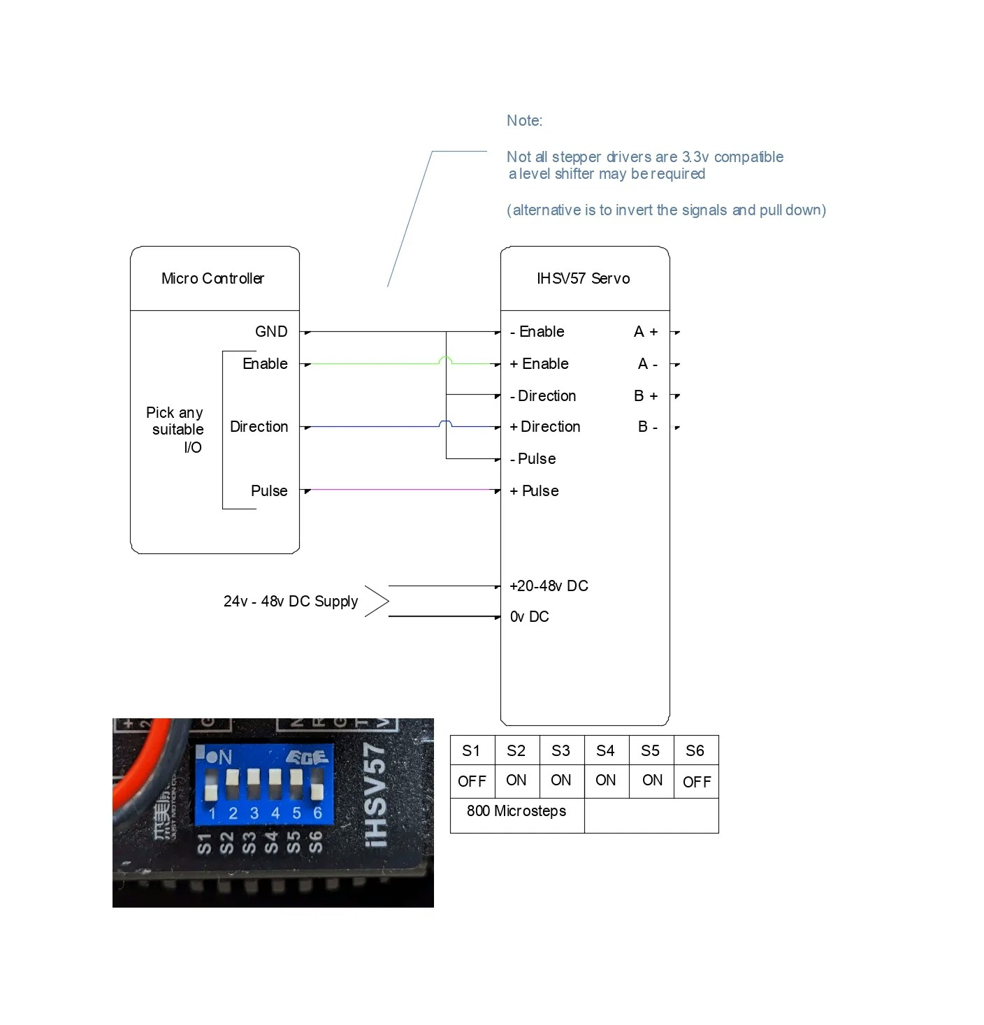 Some integrated servos accept 3.3V logic directly; others require 5V. Check your servo’s documentation— you may be able to omit the level shifter.
### Additional stepper driver options
For more designs and archived schematics, see the repository’s hardware archive:
```
/ossm/Hardware/PCB Files/Archive/
```
## Power and grounding best practices
* Use a single‑point (star) ground between ESP32, level shifter, and driver
* Keep step/direction/enable leads short; avoid running them parallel to motor power
* Twist each motor phase pair (A+/A‑ and B+/B‑) to reduce EMI
* Provide strain relief for all connectors to prevent intermittent faults
* If runs are long, consider shielded cable for control signals and connect shield to chassis/earth at one end only
## Verifying your wiring
Perform these checks before applying power to the motor driver.
Use a multimeter to confirm each signal runs from the correct ESP32 pin to the driver input.
Step, direction, and enable each show continuity from ESP32 → level shifter → driver.
Ensure no shorts exist between adjacent signal lines or between any signal and power rails.
No continuity between neighboring pins or between signals and DC+/DC‑.
Verify supply polarity and voltage at the driver terminals before connecting the motor.
Reverse polarity can instantly damage the driver. Double‑check DC+ and DC‑ orientation.
## First power‑on checklist
* With the motor disconnected, power the driver and confirm status LEDs look normal
* Connect the motor, then command a very low speed move
* Verify direction changes when commanded
* If using an encoder, confirm counts change smoothly in one direction and reverse when direction changes
You can command low‑speed movement without missed steps, oscillation, or driver faults.
## Troubleshooting
This usually indicates a logic‑level mismatch or poor signal integrity.
* The level shifter is powered on both sides (3.3V and 5V)
* Grounds are common between ESP32, level shifter, and driver
* Signal wires are short and routed away from motor power
If you are not using a level shifter, add one. If you are, verify the 5V supply on the high‑side pins.
The driver may not be receiving valid control signals.
* Check the enable input polarity; many drivers use active‑low enable
* Confirm step/direction pins match your firmware configuration
* Ensure the driver has adequate power (verify status LEDs)
Use a logic analyzer or oscilloscope to confirm step pulses at the driver input.
Electrical noise or supply instability may be affecting the control path.
* Keep signal wires separate from motor power cables
* Verify the driver supply remains within spec under load
* Add local decoupling near the driver inputs
Add 0.1 µF ceramic capacitors close to the driver’s control inputs (to ground). Use shielded cable for long signal runs.
The direction signal is inverted relative to your wiring.
Swap the direction polarity at the connector, or invert direction in firmware by changing the `INVERT_DIRECTION` setting.
Always power down and wait for capacitors to discharge before rewiring. Reversing polarity or shorting outputs can permanently damage your hardware.
Some integrated servos accept 3.3V logic directly; others require 5V. Check your servo’s documentation— you may be able to omit the level shifter.
### Additional stepper driver options
For more designs and archived schematics, see the repository’s hardware archive:
```
/ossm/Hardware/PCB Files/Archive/
```
## Power and grounding best practices
* Use a single‑point (star) ground between ESP32, level shifter, and driver
* Keep step/direction/enable leads short; avoid running them parallel to motor power
* Twist each motor phase pair (A+/A‑ and B+/B‑) to reduce EMI
* Provide strain relief for all connectors to prevent intermittent faults
* If runs are long, consider shielded cable for control signals and connect shield to chassis/earth at one end only
## Verifying your wiring
Perform these checks before applying power to the motor driver.
Use a multimeter to confirm each signal runs from the correct ESP32 pin to the driver input.
Step, direction, and enable each show continuity from ESP32 → level shifter → driver.
Ensure no shorts exist between adjacent signal lines or between any signal and power rails.
No continuity between neighboring pins or between signals and DC+/DC‑.
Verify supply polarity and voltage at the driver terminals before connecting the motor.
Reverse polarity can instantly damage the driver. Double‑check DC+ and DC‑ orientation.
## First power‑on checklist
* With the motor disconnected, power the driver and confirm status LEDs look normal
* Connect the motor, then command a very low speed move
* Verify direction changes when commanded
* If using an encoder, confirm counts change smoothly in one direction and reverse when direction changes
You can command low‑speed movement without missed steps, oscillation, or driver faults.
## Troubleshooting
This usually indicates a logic‑level mismatch or poor signal integrity.
* The level shifter is powered on both sides (3.3V and 5V)
* Grounds are common between ESP32, level shifter, and driver
* Signal wires are short and routed away from motor power
If you are not using a level shifter, add one. If you are, verify the 5V supply on the high‑side pins.
The driver may not be receiving valid control signals.
* Check the enable input polarity; many drivers use active‑low enable
* Confirm step/direction pins match your firmware configuration
* Ensure the driver has adequate power (verify status LEDs)
Use a logic analyzer or oscilloscope to confirm step pulses at the driver input.
Electrical noise or supply instability may be affecting the control path.
* Keep signal wires separate from motor power cables
* Verify the driver supply remains within spec under load
* Add local decoupling near the driver inputs
Add 0.1 µF ceramic capacitors close to the driver’s control inputs (to ground). Use shielded cable for long signal runs.
The direction signal is inverted relative to your wiring.
Swap the direction polarity at the connector, or invert direction in firmware by changing the `INVERT_DIRECTION` setting.
Always power down and wait for capacitors to discharge before rewiring. Reversing polarity or shorting outputs can permanently damage your hardware.