> ## Documentation Index
> Fetch the complete documentation index at: https://docs.researchanddesire.com/llms.txt
> Use this file to discover all available pages before exploring further.
# Wiring Your Gold Motor
> Step-by-step guide to correctly wiring your OSSM Gold Motor (57AIM30) to the OSSM PCB
This guide walks you through wiring your OSSM Gold Motor (57AIM30) to the OSSM PCB. If you purchased a motor from R+D, your kit includes all necessary cables and connectors.
## What you'll need
**Tools:**
* Small flat head screwdriver
* Wire strippers
* Snippers
**Included components:**
* Green connector (6-position screw terminal block)
* PH04 Cable (4-wire signal cable with white JST connector)
* 250mm 18AWG power cable (2-wire, red and black)
* Wiring sleeve (optional)
The green connector is a 6-position screw terminal block that accommodates all 6 wires: 2 from the power cable and 4 from the PH04 signal cable. No crimping required—simply insert stripped wires and tighten the screws.
## Wiring the green connector
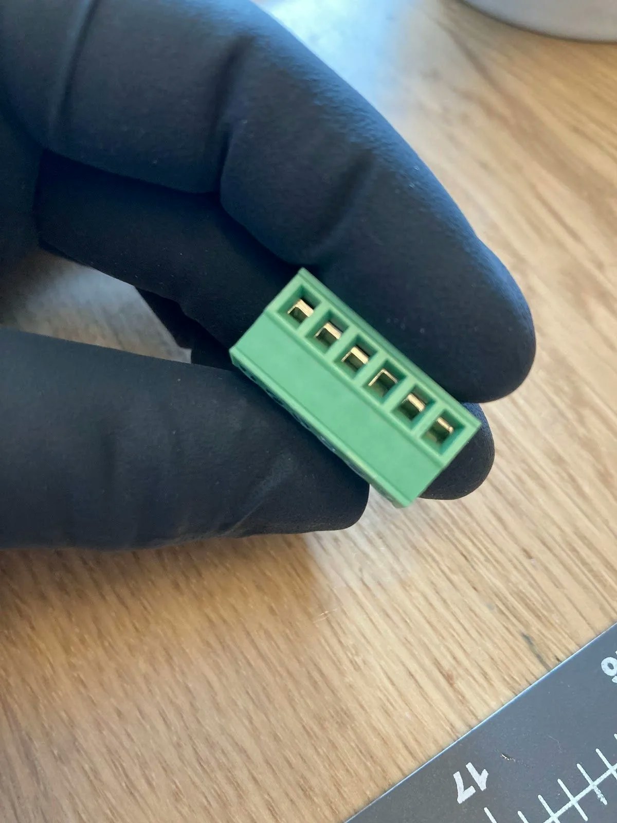
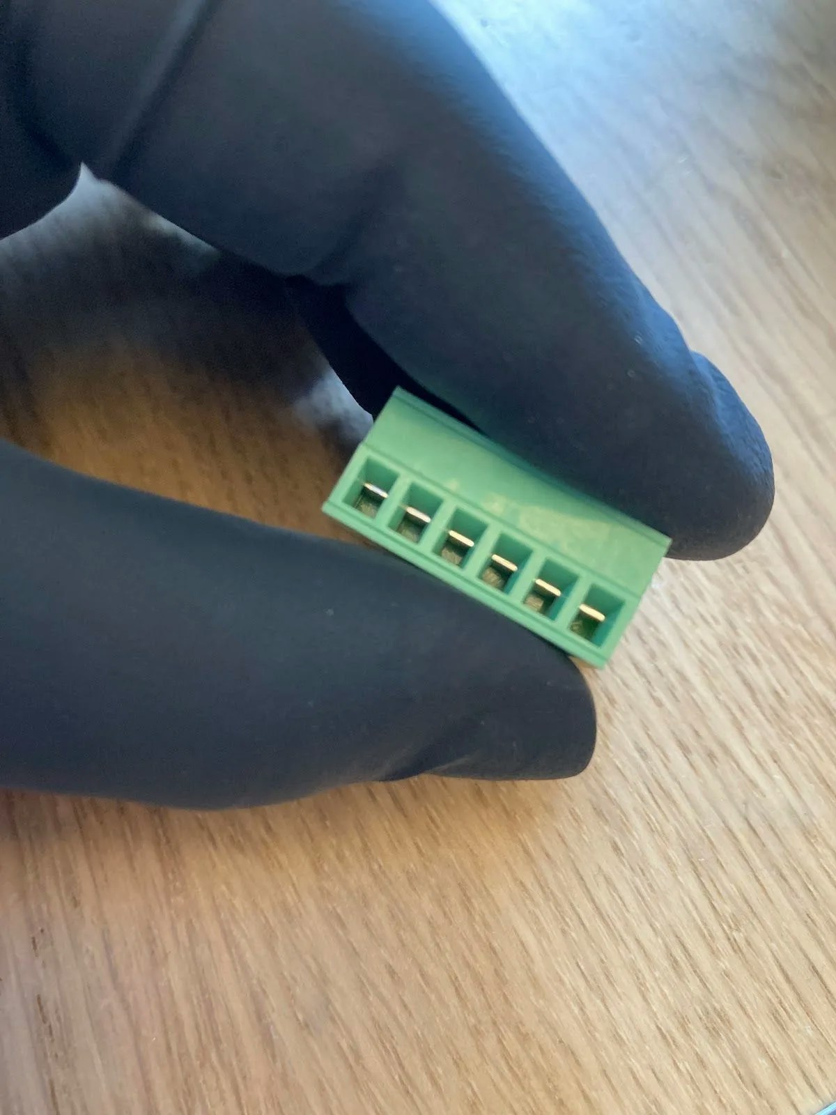
Use your screwdriver to open all terminals on the green connector. The terminals arrive in the closed position by default.
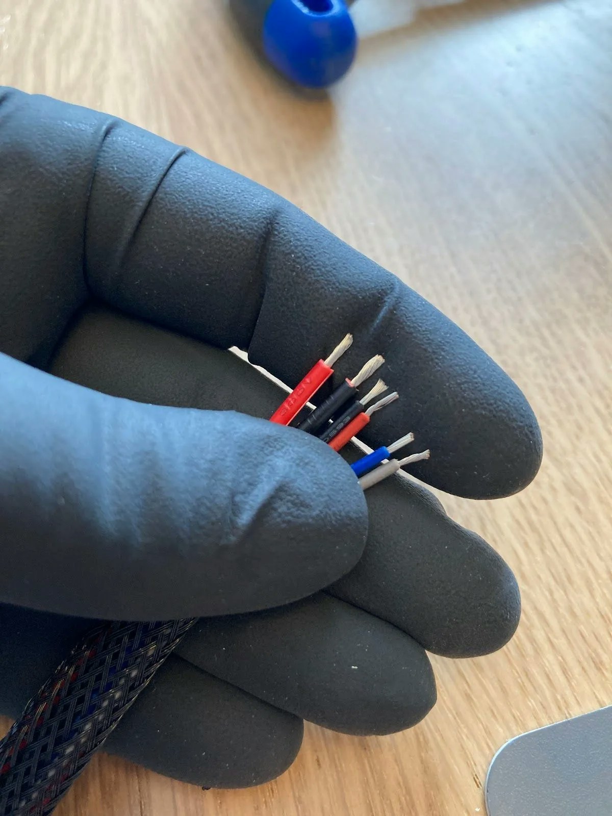 Separate the power cable wires and strip all wire ends to approximately 2-3mm (about ⅛").
If you're using a wiring sleeve, thread the wires through it before stripping the ends.
Arrange your wires in this order from left to right:
1. **Power cable:** Red, Black
2. **PH04 cable:** Black, Red, Blue, Grey
Insert the power cables (red, then black) into the first two terminals. Ensure the screws face the top of the connector.
Separate the power cable wires and strip all wire ends to approximately 2-3mm (about ⅛").
If you're using a wiring sleeve, thread the wires through it before stripping the ends.
Arrange your wires in this order from left to right:
1. **Power cable:** Red, Black
2. **PH04 cable:** Black, Red, Blue, Grey
Insert the power cables (red, then black) into the first two terminals. Ensure the screws face the top of the connector.
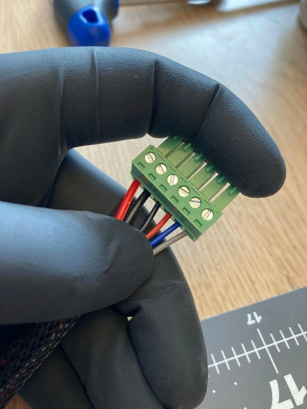
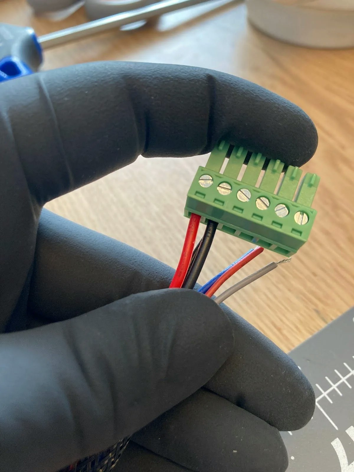 Tighten the terminal screws as firmly as possible. Loose connections can cause intermittent power issues or motor failures.
Insert the PH04 cable wires (black, red, blue, grey) into the remaining terminals and tighten each screw securely.
Your green connector is now complete and ready to plug into the motor.
## Wiring the OSSM PCB
Locate the power terminals on your OSSM PCB. They arrive in the closed position.
Tighten the terminal screws as firmly as possible. Loose connections can cause intermittent power issues or motor failures.
Insert the PH04 cable wires (black, red, blue, grey) into the remaining terminals and tighten each screw securely.
Your green connector is now complete and ready to plug into the motor.
## Wiring the OSSM PCB
Locate the power terminals on your OSSM PCB. They arrive in the closed position.
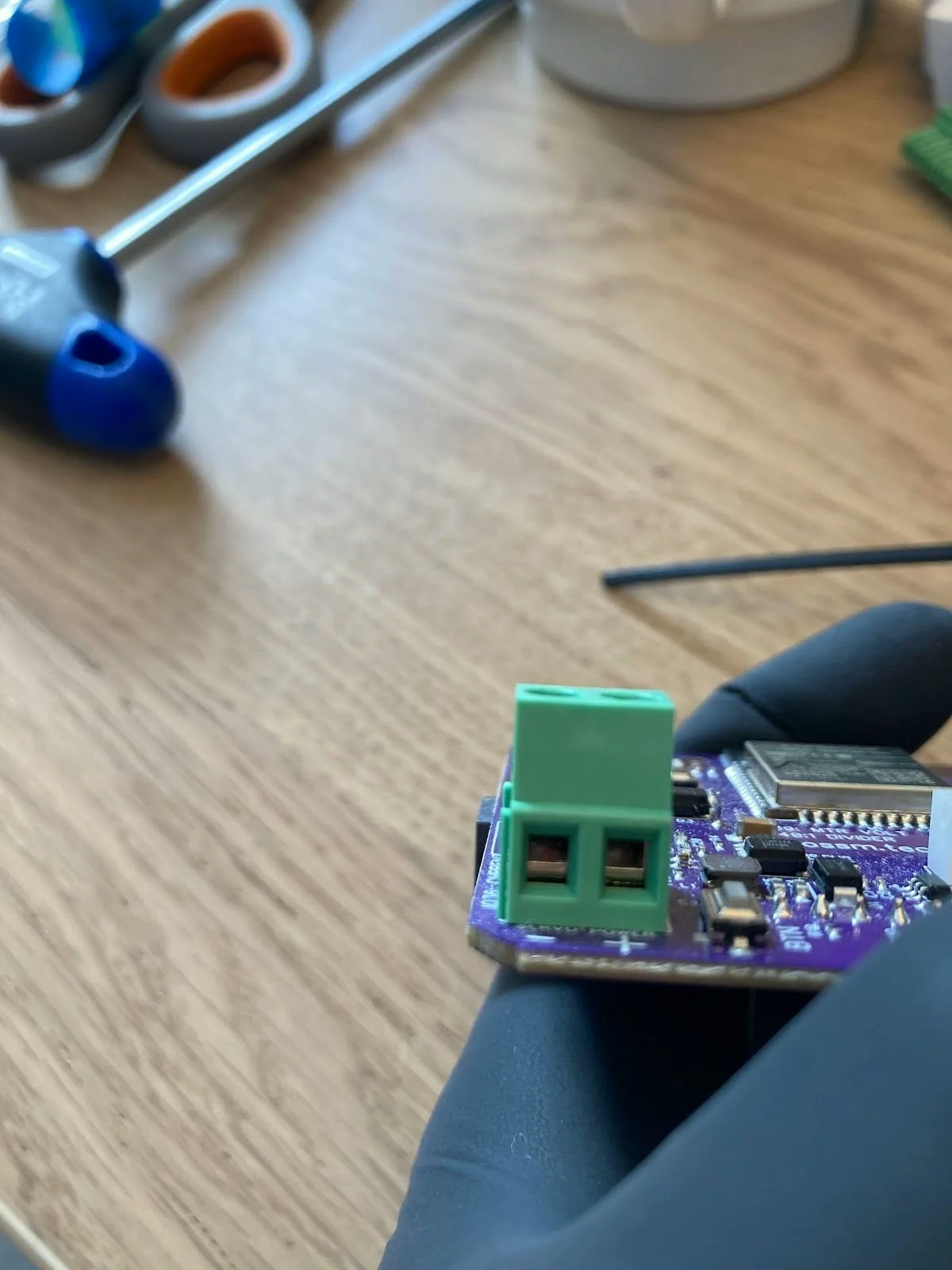
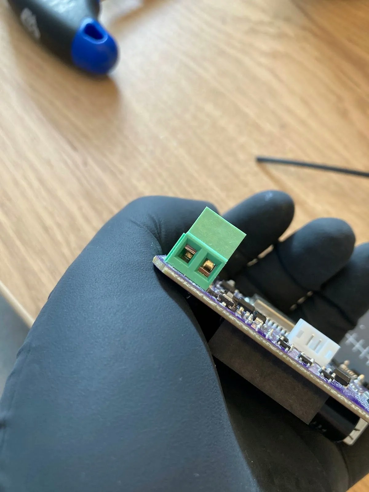 Strip and separate the other end of your power cable. Twist the exposed wire strands together to prevent splaying.
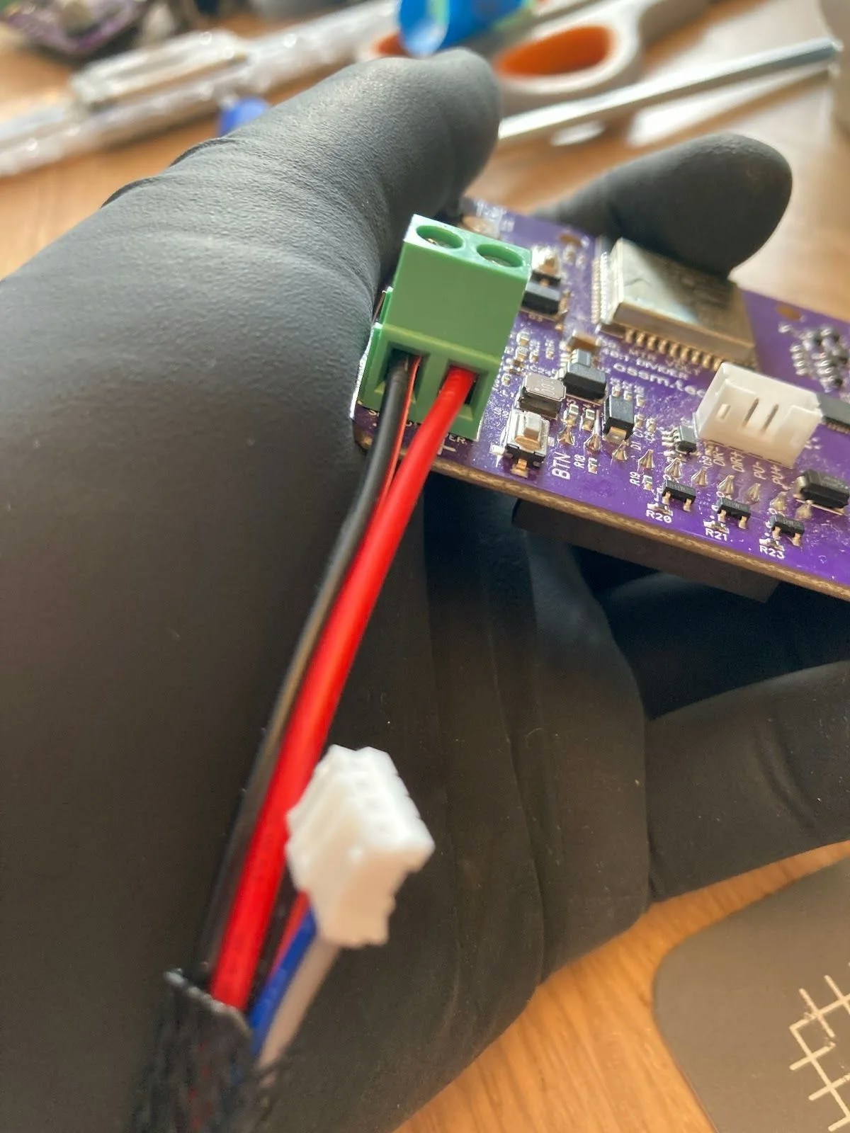
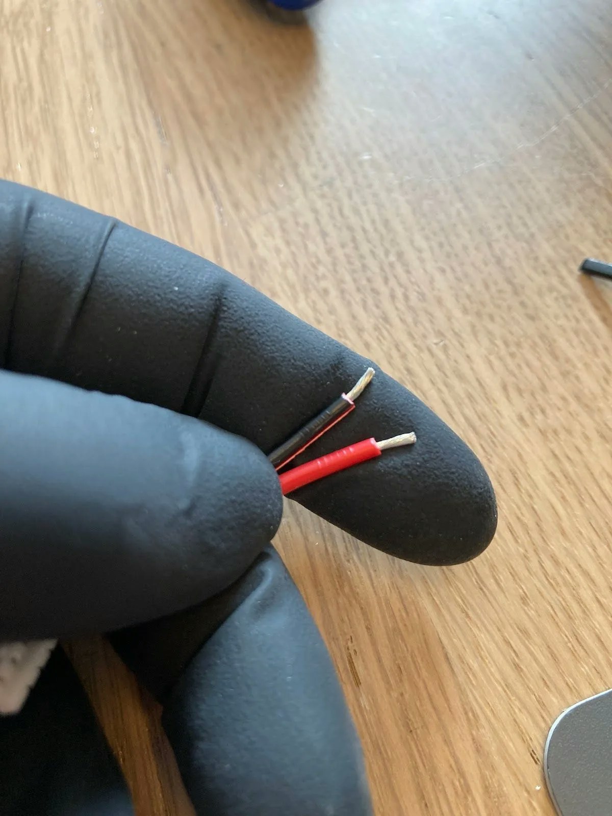 Insert the wires into the correct terminals:
* **Black wire** → `-` terminal
* **Red wire** → `+` terminal
Tighten both terminal screws securely.
1. Plug the white connector from the PH04 cable into the matching white connector on the PCB
2. Connect the green connector to the green terminal on the motor
3. Plug your 24V power supply into the board
When powered on, the motor base displays a green light and the shaft begins rotating.
## Troubleshooting
If you have your OSSM remote connected to the board during testing, the device cannot complete homing. This is expected behavior—homing requires your OSSM to be fully assembled with the rail installed.
Insert the wires into the correct terminals:
* **Black wire** → `-` terminal
* **Red wire** → `+` terminal
Tighten both terminal screws securely.
1. Plug the white connector from the PH04 cable into the matching white connector on the PCB
2. Connect the green connector to the green terminal on the motor
3. Plug your 24V power supply into the board
When powered on, the motor base displays a green light and the shaft begins rotating.
## Troubleshooting
If you have your OSSM remote connected to the board during testing, the device cannot complete homing. This is expected behavior—homing requires your OSSM to be fully assembled with the rail installed.