> ## Documentation Index
> Fetch the complete documentation index at: https://docs.researchanddesire.com/llms.txt
> Use this file to discover all available pages before exploring further.
# Overview
> Print settings, bill of materials, and assembly instructions for the OSSM actuator
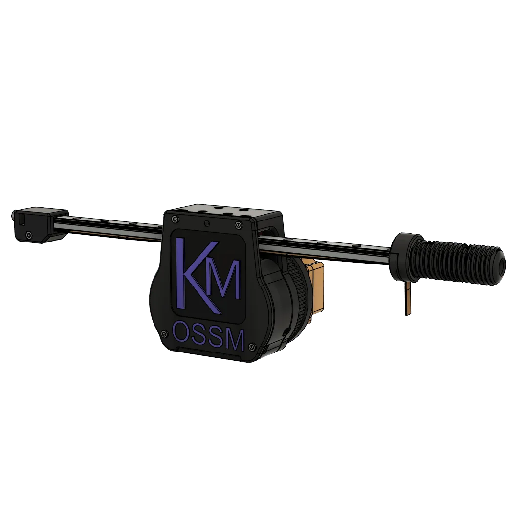 The OSSM linear actuator converts rotary motor motion into linear thrust via a GT2 belt drive on an MGN12H linear rail. This page covers printing, hardware, and assembly.
## Print Settings
| Setting | Value |
| -------------------- | --------------------- |
| Walls | 6 |
| Infill Type | Cross Hatch or Gyroid |
| Infill Percentage | 15% |
| Supports | None |
| Filament Estimate | 200g |
| Recommended Filament | PLA+ |
Print all parts in the default file orientation. Printing threaded components in other orientations causes structural weakness.
For the 24mm Clamping Thread, use 2 raft layers to improve bed adhesion.
All OSSM print files are also available on MakerWorld.
## Printed Parts
| Quantity | Part |
| -------- | ----------------------------- |
| 1 | OSSM - Body - Middle |
| 1 | OSSM - Body - Lower |
| 1 | OSSM - Belt Clamp - Tensioner |
| 1 | OSSM - Belt Clamp - Top |
| 1 | OSSM - Belt Clamp - Bottom |
| 1 | OSSM - Body - Cover |
| 1 | OSSM - 24mm Jam Nut |
| 1 | OSSM - PCB Mount Base |
| 1 | OSSM - PCB Mount Lid |
| 1 | 57AIM Ring v1.1 |
| 1 | PitClamp v1.1 Lower Standard |
| 1 | PitClamp v1.1 Upper + Handle |
| 1 | PitClamp Dogbones Hex |
| 1 | PitClamp Dogbones Round |
If you have issues printing the 24mm Clamping Thread, use the Non-standard 24mm Thread and Belt Clamp files instead. These require additional hardware:
* (Qty 2) M3x8
* (Qty 1) M3x16
* (Qty 3) M3 Hex Nut
## Bill of Materials
### Motor and Linear Rail
| Quantity | Part |
| -------- | ------------------------------------ |
| 1 | 57AIM30 Gold Motor |
| 1 | MGN12H Linear Rail (350mm suggested) |
Calculate your rail length: **desired maximum stroke + 180mm**.
You must use an MGN**12H** rail. The "H" designates a longer bearing block than "C" for greater stability. The "12" indicates a 12mm rail width.
### Hardware
| Part | Qty |
| ------------------------------------- | ---- |
| M3x8mm socket cap screw | 18 |
| M3x20mm socket cap screw | 3 |
| M3 hex nut | 10 |
| M4x25mm socket cap screw | 2 |
| M4 hex nut | 3 |
| M5x20mm socket cap screw | 6 |
| M5x35mm socket cap screw | 4 |
| M5 hex nut | 8 |
| M6x16mm socket cap screw | 2 |
| M6 T-Nut for 30x30mm t-slot extrusion | 2 |
| 5x11x4mm bearings | 6 |
| 8mm bore 20T pulley | 1 |
| 10mm GT2 belt | 50cm |
## Assembly
The OSSM linear actuator converts rotary motor motion into linear thrust via a GT2 belt drive on an MGN12H linear rail. This page covers printing, hardware, and assembly.
## Print Settings
| Setting | Value |
| -------------------- | --------------------- |
| Walls | 6 |
| Infill Type | Cross Hatch or Gyroid |
| Infill Percentage | 15% |
| Supports | None |
| Filament Estimate | 200g |
| Recommended Filament | PLA+ |
Print all parts in the default file orientation. Printing threaded components in other orientations causes structural weakness.
For the 24mm Clamping Thread, use 2 raft layers to improve bed adhesion.
All OSSM print files are also available on MakerWorld.
## Printed Parts
| Quantity | Part |
| -------- | ----------------------------- |
| 1 | OSSM - Body - Middle |
| 1 | OSSM - Body - Lower |
| 1 | OSSM - Belt Clamp - Tensioner |
| 1 | OSSM - Belt Clamp - Top |
| 1 | OSSM - Belt Clamp - Bottom |
| 1 | OSSM - Body - Cover |
| 1 | OSSM - 24mm Jam Nut |
| 1 | OSSM - PCB Mount Base |
| 1 | OSSM - PCB Mount Lid |
| 1 | 57AIM Ring v1.1 |
| 1 | PitClamp v1.1 Lower Standard |
| 1 | PitClamp v1.1 Upper + Handle |
| 1 | PitClamp Dogbones Hex |
| 1 | PitClamp Dogbones Round |
If you have issues printing the 24mm Clamping Thread, use the Non-standard 24mm Thread and Belt Clamp files instead. These require additional hardware:
* (Qty 2) M3x8
* (Qty 1) M3x16
* (Qty 3) M3 Hex Nut
## Bill of Materials
### Motor and Linear Rail
| Quantity | Part |
| -------- | ------------------------------------ |
| 1 | 57AIM30 Gold Motor |
| 1 | MGN12H Linear Rail (350mm suggested) |
Calculate your rail length: **desired maximum stroke + 180mm**.
You must use an MGN**12H** rail. The "H" designates a longer bearing block than "C" for greater stability. The "12" indicates a 12mm rail width.
### Hardware
| Part | Qty |
| ------------------------------------- | ---- |
| M3x8mm socket cap screw | 18 |
| M3x20mm socket cap screw | 3 |
| M3 hex nut | 10 |
| M4x25mm socket cap screw | 2 |
| M4 hex nut | 3 |
| M5x20mm socket cap screw | 6 |
| M5x35mm socket cap screw | 4 |
| M5 hex nut | 8 |
| M6x16mm socket cap screw | 2 |
| M6 T-Nut for 30x30mm t-slot extrusion | 2 |
| 5x11x4mm bearings | 6 |
| 8mm bore 20T pulley | 1 |
| 10mm GT2 belt | 50cm |
## Assembly
 ### Before You Begin
* Ensure all printed threads are clean and free of stringing. Test-fit the 24mm threaded parts by hand only.
* Lightly deburr belt paths and bearing seats on printed parts as needed.
* Gather metric hex keys and a small flathead screwdriver for set screws and terminal blocks.
Do not power the actuator until you complete belt routing and verify smooth motion. Avoid forcing the rail carriage — binding indicates misalignment.
### Build Steps
Verify your rail matches the required spec (MGN12H). Slide the carriage through its full travel; it should feel smooth with no catches.
Carriage moves freely across the entire rail without binding.
Position Body - Bottom and Body - Middle. Align mounting holes and loosely fasten the parts so you can make minor adjustments during alignment. Add Body - Cover later after belt routing.
Start all screws before tightening to maintain alignment.
Press-fit the MR115-2RS bearings into the Belt Tensioner and any designated idler pockets in the body. The bearings should seat flush and spin freely.
All bearings are fully seated and rotate without rubbing printed walls.
Fit the 20T GT2 pulley (8mm bore, 10mm width) on the drive shaft and align it with the belt path. Secure set screws against a flat on the shaft if available.
Keep the pulley aligned with the belt centerline to prevent tracking issues.
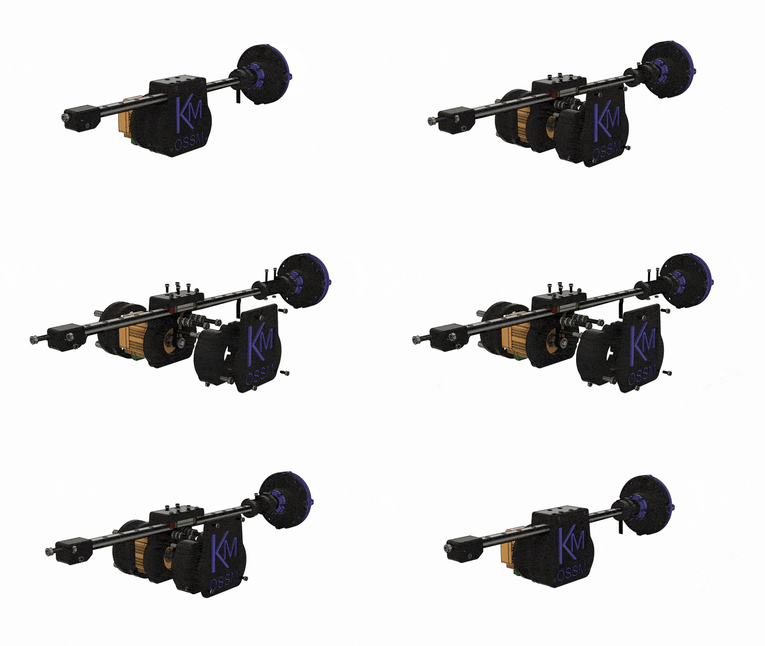
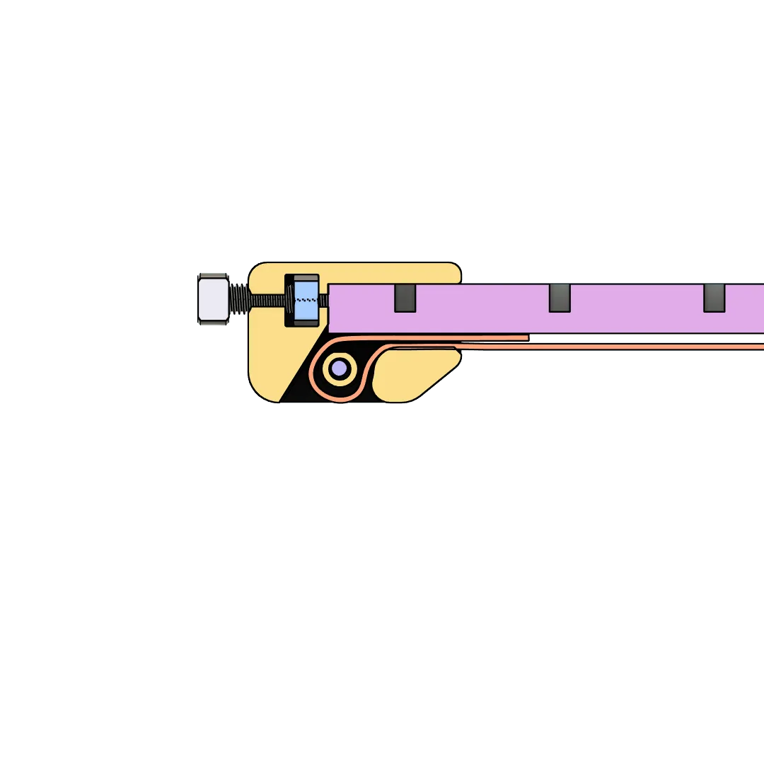
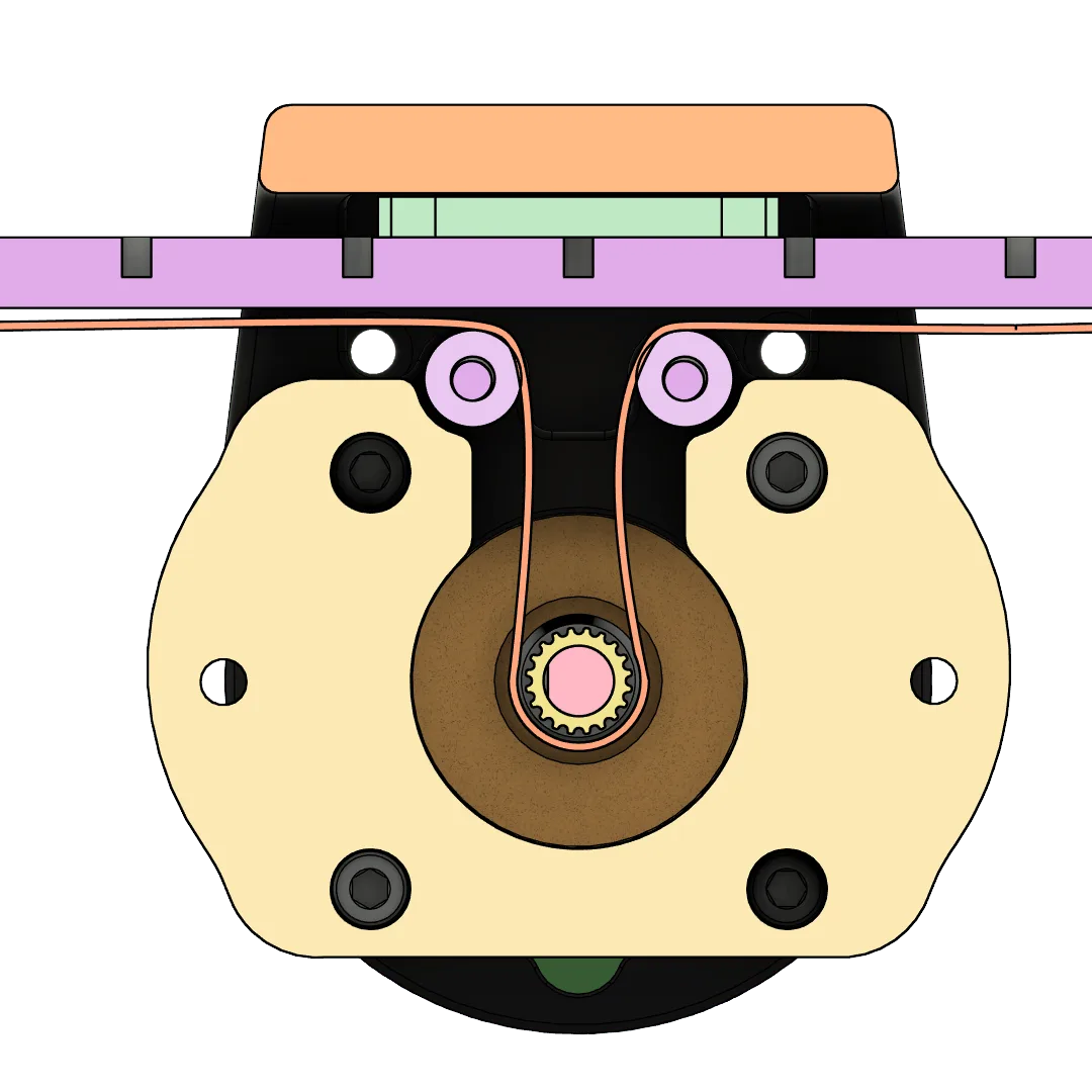
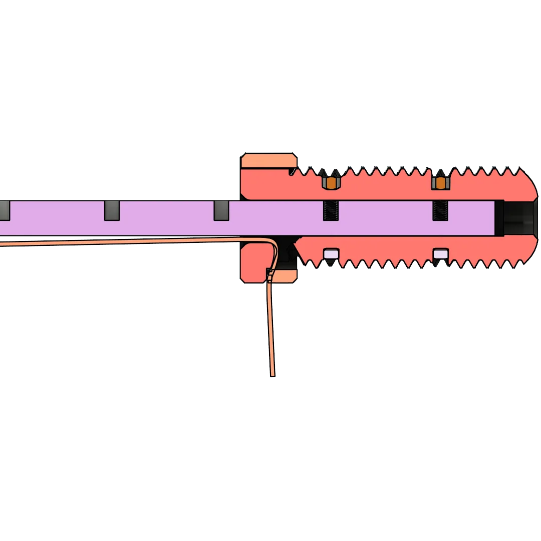
Feed the 10mm GT2 belt through the body following the Tensioner → Body → Belt Clamp path. Leave equal tail length at the clamp for final tensioning.
Belt teeth fully engage pulley teeth; belt is not twisted.
Assemble the 24mm Clamping Thread - End Effector and Belt Clamp with the two 24mm 5-sided nuts. Hand-tighten only during initial fit.
If your print has poor first-layer adhesion on these parts, use a raft (2 layers recommended) and reprint.
Use the Belt Tensioner to remove slack until the belt is taut and tracks true during manual motion. Once satisfied, install the Body - Cover and tighten all hardware progressively.
With light hand motion, the carriage moves smoothly and returns without skipping teeth.
### Belt Routing


Route the GT2 timing belt through the actuator body following these reference images:
### Before You Begin
* Ensure all printed threads are clean and free of stringing. Test-fit the 24mm threaded parts by hand only.
* Lightly deburr belt paths and bearing seats on printed parts as needed.
* Gather metric hex keys and a small flathead screwdriver for set screws and terminal blocks.
Do not power the actuator until you complete belt routing and verify smooth motion. Avoid forcing the rail carriage — binding indicates misalignment.
### Build Steps
Verify your rail matches the required spec (MGN12H). Slide the carriage through its full travel; it should feel smooth with no catches.
Carriage moves freely across the entire rail without binding.
Position Body - Bottom and Body - Middle. Align mounting holes and loosely fasten the parts so you can make minor adjustments during alignment. Add Body - Cover later after belt routing.
Start all screws before tightening to maintain alignment.
Press-fit the MR115-2RS bearings into the Belt Tensioner and any designated idler pockets in the body. The bearings should seat flush and spin freely.
All bearings are fully seated and rotate without rubbing printed walls.
Fit the 20T GT2 pulley (8mm bore, 10mm width) on the drive shaft and align it with the belt path. Secure set screws against a flat on the shaft if available.
Keep the pulley aligned with the belt centerline to prevent tracking issues.
Feed the 10mm GT2 belt through the body following the Tensioner → Body → Belt Clamp path. Leave equal tail length at the clamp for final tensioning.
Belt teeth fully engage pulley teeth; belt is not twisted.
Assemble the 24mm Clamping Thread - End Effector and Belt Clamp with the two 24mm 5-sided nuts. Hand-tighten only during initial fit.
If your print has poor first-layer adhesion on these parts, use a raft (2 layers recommended) and reprint.
Use the Belt Tensioner to remove slack until the belt is taut and tracks true during manual motion. Once satisfied, install the Body - Cover and tighten all hardware progressively.
With light hand motion, the carriage moves smoothly and returns without skipping teeth.
### Belt Routing
Route the GT2 timing belt through the actuator body following these reference images:
 ## Next Steps
Use the web flasher to install the latest firmware on your OSSM or RADR.
Connect the Gold Motor (57AIM30) correctly before first power-on.
Configure third-party motors before first use.
## Next Steps
Use the web flasher to install the latest firmware on your OSSM or RADR.
Connect the Gold Motor (57AIM30) correctly before first power-on.
Configure third-party motors before first use.