> ## Documentation Index
> Fetch the complete documentation index at: https://docs.researchanddesire.com/llms.txt
> Use this file to discover all available pages before exploring further.
# PCB Overview
> Technical documentation for the RADR main PCB (OSSM Wireless v0.4)
This section covers the RADR main PCB design, including schematics, component specifications, and manufacturing files.
## Board Overview
| Specification | Value |
| --------------- | ------------------- |
| Board Name | OSSM Wireless |
| Version | v0.4 |
| Microcontroller | ESP32-S3 with PSRAM |
| Design Software | Altium Designer |
| Layer Count | 2 (estimated) |
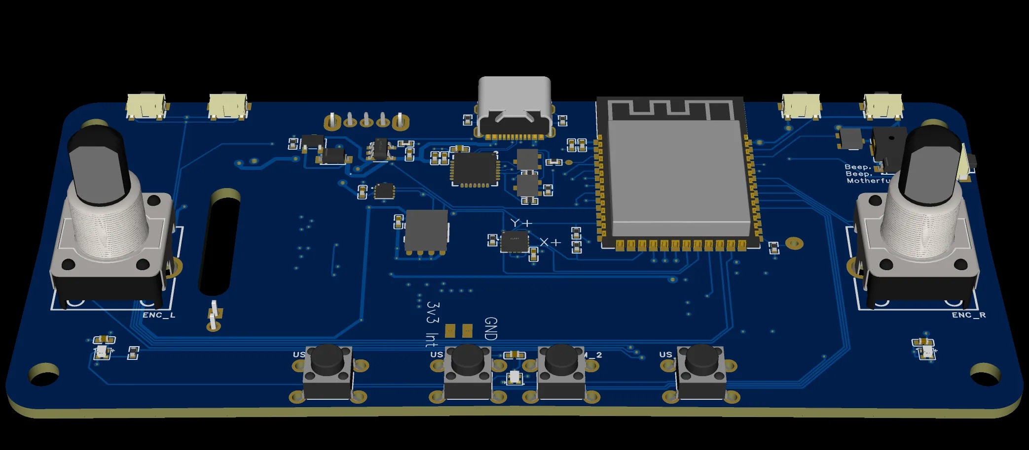
The RADR PCB integrates all electronics required for a standalone wireless remote controller, including the microcontroller, display interface, power management, user inputs, and feedback systems.
 ## Core Components
### Microcontroller
| Parameter | Value |
| ----------------- | ------------------- |
| MCU | ESP32-S3 |
| Memory | Includes PSRAM |
| Wireless | WiFi + Bluetooth LE |
| Operating Voltage | 3.3V |
The ESP32-S3 provides:
* Dual-core Xtensa LX7 processor
* Integrated Bluetooth Low Energy for device communication
* Sufficient GPIO for all inputs, outputs, and peripherals
* Low-power sleep modes for battery conservation
### Power Management
| Component | Function |
| --------------- | ------------------------------- |
| USB-C Connector | 5V charging input |
| Charging IC | LiPo battery charging |
| MAX17048 | Fuel gauge (battery monitoring) |
| LDO/Regulator | 3.3V system power |
The power system supports:
* USB-C charging (5V input)
* Hardware charging LED indicator
* Precision battery percentage via I²C fuel gauge
* Deep sleep current \< 100μA
### Display Interface
| Parameter | Value |
| ------------ | ---------------- |
| Display Type | TFT LCD |
| Resolution | 320 x 240 pixels |
| Color Depth | 16-bit (RGB565) |
| Interface | SPI |
| Backlight | PWM-controlled |
### User Inputs
| Input | Type | GPIO |
| ------------------- | ---------------- | ----------- |
| Left Encoder | Rotary + Push | GPIO 10, 11 |
| Right Encoder | Rotary + Push | GPIO 42, 41 |
| Left Shoulder | Momentary switch | GPIO 48 |
| Right Shoulder | Momentary switch | GPIO 1 |
| Under-Screen Left | Momentary switch | GPIO 38 |
| Under-Screen Center | Momentary switch | GPIO 39 |
| Under-Screen Right | Momentary switch | GPIO 40 |
GPIO assignments shown are for v0.4 boards with PSRAM. Earlier v1.x boards use different pins for the left encoder (GPIO 35, 36) and LEDs (GPIO 37).
### Feedback Outputs
| Component | Type | GPIO |
| --------------- | ---------------- | ------- |
| Status LEDs | WS2812B RGB (x3) | GPIO 12 |
| Buzzer | Piezoelectric | GPIO 2 |
| Vibration Motor | ERM motor | GPIO 47 |
### Expansion
| Connector | Interface | Purpose |
| --------- | --------- | ---------------------------- |
| QWIIC | I²C | External sensors/peripherals |
| USB-C | USB 2.0 | Programming and charging |
## Schematic Sections
The schematic is organized into functional blocks:
| Section | Description |
| --------- | ----------------------------------------------------- |
| Power | USB-C input, charging circuit, voltage regulation |
| MCU | ESP32-S3, crystal, reset, boot selection |
| Display | TFT LCD connector, backlight driver |
| Inputs | Rotary encoders, buttons, pull-up/pull-down resistors |
| Feedback | LED data line, buzzer driver, motor driver |
| Battery | MAX17048 fuel gauge, battery connector |
| Expansion | QWIIC connector, programming header |
## PCB Layout Considerations
### Component Placement
* **MCU** positioned centrally for balanced trace routing
* **USB-C** connector at board edge for accessibility
* **Display connector** oriented for ribbon cable routing to enclosure
* **Battery connector** positioned for internal battery placement
* **QWIIC connector** accessible for expansion modules
### Antenna Considerations
The ESP32-S3 uses an integrated PCB antenna or external antenna (version dependent). The antenna area should be kept clear of:
* Ground planes directly beneath
* Metal enclosure proximity
* High-frequency switching signals
Do not place components or route traces in the antenna keepout zone. This significantly degrades wireless performance.
## Design Files
All design files are available in the GitHub repository:
| File | Format | Description |
| ----------------------------------------- | --------------- | ----------------------------------------------- |
| PCB - OSSM Wireless v0.4.pcbdoc | Altium Designer | PCB layout with copper, silkscreen, drill files |
| Schematic - OSSM Wireless V0.4.schdoc | Altium Designer | Full schematic capture |
| RADR Schematic - OSSM Wireless V0.4.pdf | PDF | Printable schematic reference |
| RADR BOM - OSSM Wireless - v0.4 - S3.xlsx | Excel | Bill of Materials with part numbers |
| RADR PCB render.png | PNG | 3D render of assembled board |
Access Altium project files, Gerbers, and BOM on GitHub.
## Manufacturing
### PCB Fabrication
Recommended specifications for ordering:
| Parameter | Value |
| -------------- | ------------ |
| Layers | 2 |
| Thickness | 1.6mm |
| Surface Finish | HASL or ENIG |
| Copper Weight | 1oz |
| Solder Mask | Any color |
| Silkscreen | White |
### Assembly Options
| Method | Recommended For |
| ------------- | ------------------------ |
| Hand Assembly | Prototypes, single units |
| PCBA Service | Production quantities |
Services like JLCPCB and PCBWay offer combined PCB fabrication and assembly. Upload the Gerbers and BOM for a turnkey solution.
### Critical Components
These components require careful attention during assembly:
| Component | Notes |
| --------------- | ----------------------------------------------- |
| ESP32-S3 Module | Check orientation, ensure all pads are soldered |
| USB-C Connector | Requires precise alignment, check for shorts |
| MAX17048 | Small QFN package, needs proper reflow |
| WS2812B LEDs | Heat-sensitive, observe reflow profile |
## Version History
| Version | Changes |
| ------- | ----------------------------- |
| v0.4 | Current release with ESP32-S3 |
Version v0.4 uses the ESP32-S3 variant. The "S3" suffix in the BOM filename indicates this variant.
## Troubleshooting
* Check USB-C connection and cable
* Verify 3.3V regulator output
* Check for shorts on power rails
* Ensure battery is connected and charged
* Verify ribbon cable connection
* Check SPI signals with oscilloscope
* Confirm backlight PWM signal
* Test display power rails
* Check antenna area for shorts or bridges
* Verify ESP32-S3 is programmed correctly
* Ensure no metal near antenna zone
* Test with RF shield removed (if applicable)
* Verify USB-C CC resistors are present
* Check charging IC connections
* Measure battery voltage at connector
* Confirm charging LED circuit
* Check pull-up/pull-down resistors
* Verify GPIO assignments in firmware
* Test continuity from button to MCU
* Check for cold solder joints
## Related Documentation
Complete hardware specifications and GPIO mappings.
Detailed power management and charging documentation.
3D printed enclosure that houses the PCB.
LED, buzzer, and vibration motor details.
## Core Components
### Microcontroller
| Parameter | Value |
| ----------------- | ------------------- |
| MCU | ESP32-S3 |
| Memory | Includes PSRAM |
| Wireless | WiFi + Bluetooth LE |
| Operating Voltage | 3.3V |
The ESP32-S3 provides:
* Dual-core Xtensa LX7 processor
* Integrated Bluetooth Low Energy for device communication
* Sufficient GPIO for all inputs, outputs, and peripherals
* Low-power sleep modes for battery conservation
### Power Management
| Component | Function |
| --------------- | ------------------------------- |
| USB-C Connector | 5V charging input |
| Charging IC | LiPo battery charging |
| MAX17048 | Fuel gauge (battery monitoring) |
| LDO/Regulator | 3.3V system power |
The power system supports:
* USB-C charging (5V input)
* Hardware charging LED indicator
* Precision battery percentage via I²C fuel gauge
* Deep sleep current \< 100μA
### Display Interface
| Parameter | Value |
| ------------ | ---------------- |
| Display Type | TFT LCD |
| Resolution | 320 x 240 pixels |
| Color Depth | 16-bit (RGB565) |
| Interface | SPI |
| Backlight | PWM-controlled |
### User Inputs
| Input | Type | GPIO |
| ------------------- | ---------------- | ----------- |
| Left Encoder | Rotary + Push | GPIO 10, 11 |
| Right Encoder | Rotary + Push | GPIO 42, 41 |
| Left Shoulder | Momentary switch | GPIO 48 |
| Right Shoulder | Momentary switch | GPIO 1 |
| Under-Screen Left | Momentary switch | GPIO 38 |
| Under-Screen Center | Momentary switch | GPIO 39 |
| Under-Screen Right | Momentary switch | GPIO 40 |
GPIO assignments shown are for v0.4 boards with PSRAM. Earlier v1.x boards use different pins for the left encoder (GPIO 35, 36) and LEDs (GPIO 37).
### Feedback Outputs
| Component | Type | GPIO |
| --------------- | ---------------- | ------- |
| Status LEDs | WS2812B RGB (x3) | GPIO 12 |
| Buzzer | Piezoelectric | GPIO 2 |
| Vibration Motor | ERM motor | GPIO 47 |
### Expansion
| Connector | Interface | Purpose |
| --------- | --------- | ---------------------------- |
| QWIIC | I²C | External sensors/peripherals |
| USB-C | USB 2.0 | Programming and charging |
## Schematic Sections
The schematic is organized into functional blocks:
| Section | Description |
| --------- | ----------------------------------------------------- |
| Power | USB-C input, charging circuit, voltage regulation |
| MCU | ESP32-S3, crystal, reset, boot selection |
| Display | TFT LCD connector, backlight driver |
| Inputs | Rotary encoders, buttons, pull-up/pull-down resistors |
| Feedback | LED data line, buzzer driver, motor driver |
| Battery | MAX17048 fuel gauge, battery connector |
| Expansion | QWIIC connector, programming header |
## PCB Layout Considerations
### Component Placement
* **MCU** positioned centrally for balanced trace routing
* **USB-C** connector at board edge for accessibility
* **Display connector** oriented for ribbon cable routing to enclosure
* **Battery connector** positioned for internal battery placement
* **QWIIC connector** accessible for expansion modules
### Antenna Considerations
The ESP32-S3 uses an integrated PCB antenna or external antenna (version dependent). The antenna area should be kept clear of:
* Ground planes directly beneath
* Metal enclosure proximity
* High-frequency switching signals
Do not place components or route traces in the antenna keepout zone. This significantly degrades wireless performance.
## Design Files
All design files are available in the GitHub repository:
| File | Format | Description |
| ----------------------------------------- | --------------- | ----------------------------------------------- |
| PCB - OSSM Wireless v0.4.pcbdoc | Altium Designer | PCB layout with copper, silkscreen, drill files |
| Schematic - OSSM Wireless V0.4.schdoc | Altium Designer | Full schematic capture |
| RADR Schematic - OSSM Wireless V0.4.pdf | PDF | Printable schematic reference |
| RADR BOM - OSSM Wireless - v0.4 - S3.xlsx | Excel | Bill of Materials with part numbers |
| RADR PCB render.png | PNG | 3D render of assembled board |
Access Altium project files, Gerbers, and BOM on GitHub.
## Manufacturing
### PCB Fabrication
Recommended specifications for ordering:
| Parameter | Value |
| -------------- | ------------ |
| Layers | 2 |
| Thickness | 1.6mm |
| Surface Finish | HASL or ENIG |
| Copper Weight | 1oz |
| Solder Mask | Any color |
| Silkscreen | White |
### Assembly Options
| Method | Recommended For |
| ------------- | ------------------------ |
| Hand Assembly | Prototypes, single units |
| PCBA Service | Production quantities |
Services like JLCPCB and PCBWay offer combined PCB fabrication and assembly. Upload the Gerbers and BOM for a turnkey solution.
### Critical Components
These components require careful attention during assembly:
| Component | Notes |
| --------------- | ----------------------------------------------- |
| ESP32-S3 Module | Check orientation, ensure all pads are soldered |
| USB-C Connector | Requires precise alignment, check for shorts |
| MAX17048 | Small QFN package, needs proper reflow |
| WS2812B LEDs | Heat-sensitive, observe reflow profile |
## Version History
| Version | Changes |
| ------- | ----------------------------- |
| v0.4 | Current release with ESP32-S3 |
Version v0.4 uses the ESP32-S3 variant. The "S3" suffix in the BOM filename indicates this variant.
## Troubleshooting
* Check USB-C connection and cable
* Verify 3.3V regulator output
* Check for shorts on power rails
* Ensure battery is connected and charged
* Verify ribbon cable connection
* Check SPI signals with oscilloscope
* Confirm backlight PWM signal
* Test display power rails
* Check antenna area for shorts or bridges
* Verify ESP32-S3 is programmed correctly
* Ensure no metal near antenna zone
* Test with RF shield removed (if applicable)
* Verify USB-C CC resistors are present
* Check charging IC connections
* Measure battery voltage at connector
* Confirm charging LED circuit
* Check pull-up/pull-down resistors
* Verify GPIO assignments in firmware
* Test continuity from button to MCU
* Check for cold solder joints
## Related Documentation
Complete hardware specifications and GPIO mappings.
Detailed power management and charging documentation.
3D printed enclosure that houses the PCB.
LED, buzzer, and vibration motor details.