

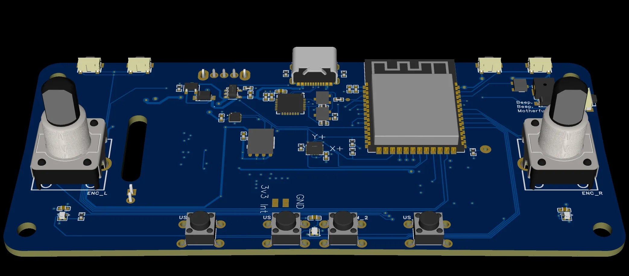
Board Overview
The RADR PCB integrates all electronics required for a standalone wireless remote controller, including the microcontroller, display interface, power management, user inputs, and feedback systems.
Core Components
Microcontroller
The ESP32-S3 provides:
- Dual-core Xtensa LX7 processor
- Integrated Bluetooth Low Energy for device communication
- Sufficient GPIO for all inputs, outputs, and peripherals
- Low-power sleep modes for battery conservation
Power Management
The power system supports:
- USB-C charging (5V input)
- Hardware charging LED indicator
- Precision battery percentage via I²C fuel gauge
- Deep sleep current < 100μA
Display Interface
User Inputs
GPIO assignments shown are for v0.4 boards with PSRAM. Earlier v1.x boards use different pins for the left encoder (GPIO 35, 36) and LEDs (GPIO 37).
Feedback Outputs
Expansion
Schematic Sections
The schematic is organized into functional blocks:PCB Layout Considerations
Component Placement
- MCU positioned centrally for balanced trace routing
- USB-C connector at board edge for accessibility
- Display connector oriented for ribbon cable routing to enclosure
- Battery connector positioned for internal battery placement
- QWIIC connector accessible for expansion modules
Antenna Considerations
The ESP32-S3 uses an integrated PCB antenna or external antenna (version dependent). The antenna area should be kept clear of:- Ground planes directly beneath
- Metal enclosure proximity
- High-frequency switching signals
Design Files
All design files are available in the GitHub repository:Download Design Files
Access Altium project files, Gerbers, and BOM on GitHub.
Manufacturing
PCB Fabrication
Recommended specifications for ordering:Assembly Options
Critical Components
These components require careful attention during assembly:Version History
Version v0.4 uses the ESP32-S3 variant. The “S3” suffix in the BOM filename indicates this variant.
Troubleshooting
Board doesn't power on
Board doesn't power on
- Check USB-C connection and cable
- Verify 3.3V regulator output
- Check for shorts on power rails
- Ensure battery is connected and charged
Display not working
Display not working
- Verify ribbon cable connection
- Check SPI signals with oscilloscope
- Confirm backlight PWM signal
- Test display power rails
Bluetooth not connecting
Bluetooth not connecting
- Check antenna area for shorts or bridges
- Verify ESP32-S3 is programmed correctly
- Ensure no metal near antenna zone
- Test with RF shield removed (if applicable)
Battery not charging
Battery not charging
- Verify USB-C CC resistors are present
- Check charging IC connections
- Measure battery voltage at connector
- Confirm charging LED circuit
Related Documentation
Hardware Overview
Complete hardware specifications and GPIO mappings.
Battery & Power
Detailed power management and charging documentation.
Printed Parts
3D printed enclosure that houses the PCB.
Feedback Systems
LED, buzzer, and vibration motor details.