Step-by-step guide to correctly wiring your OSSM Gold Motor (57AIM30) to the OSSM PCB
This guide walks you through wiring your OSSM Gold Motor (57AIM30) to the OSSM PCB. If you purchased a motor from R+D, your kit includes all necessary cables and connectors.
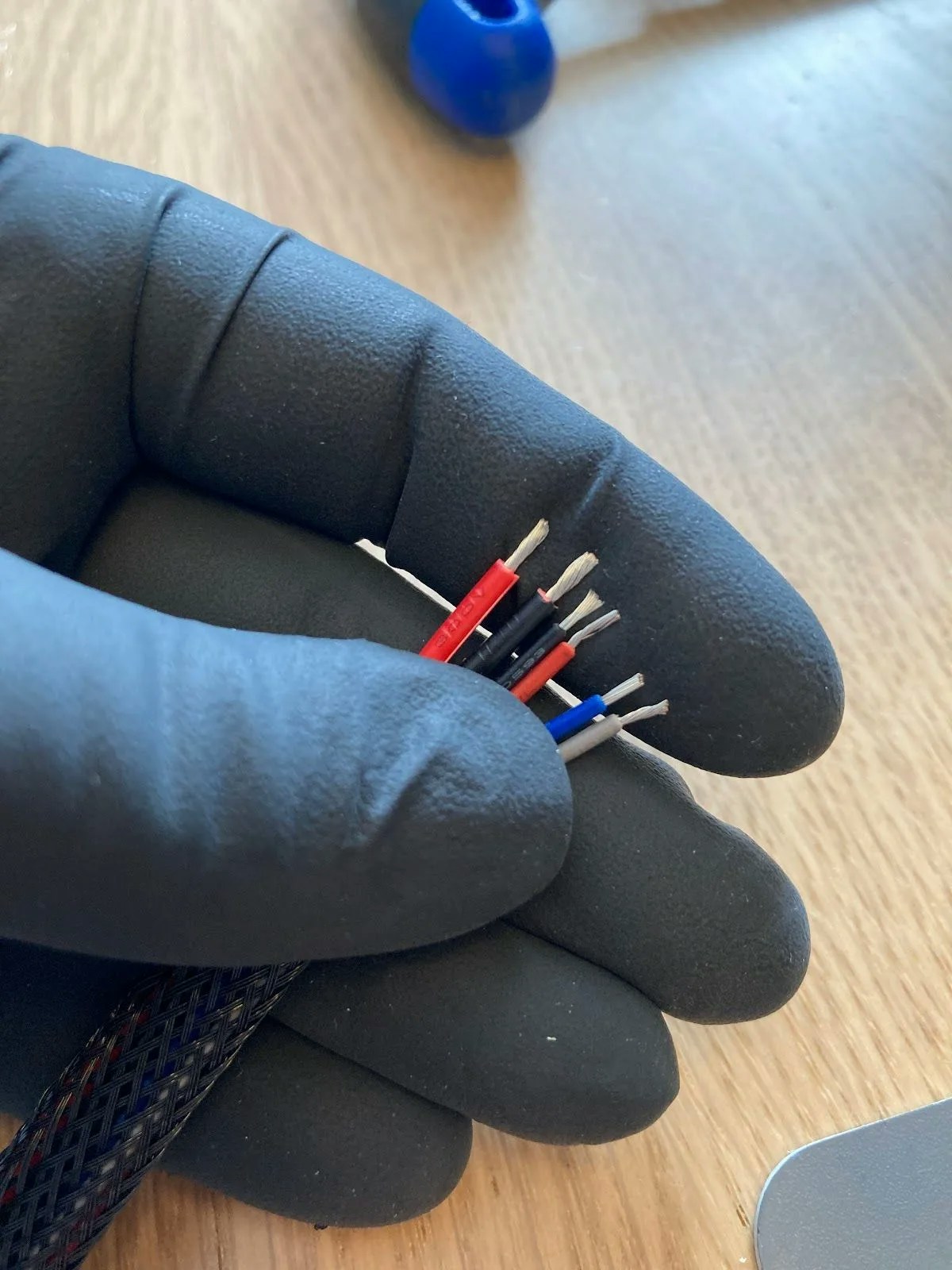
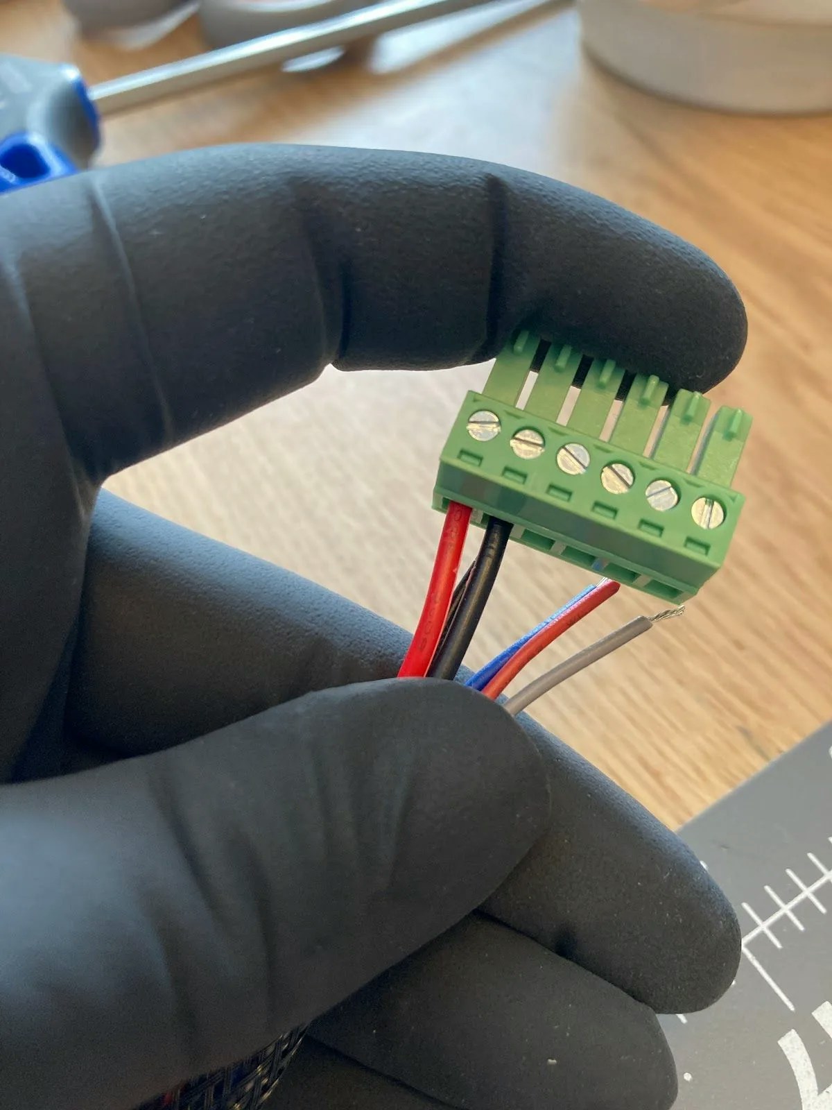
PH04 Cable (4-wire signal cable with white JST connector)
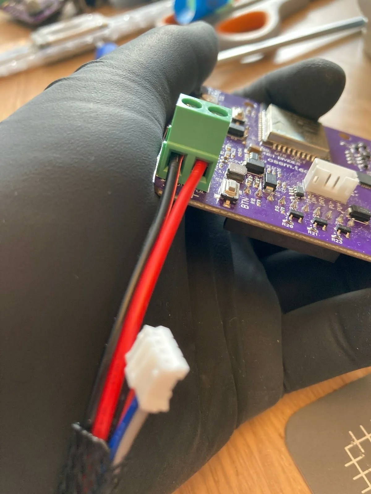
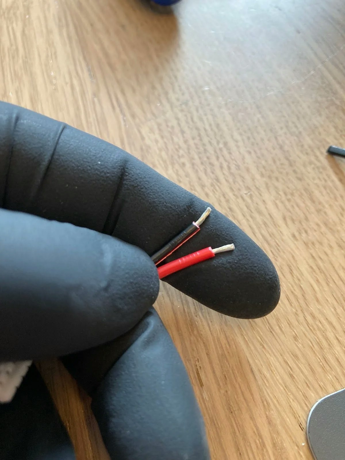
250mm 18AWG power cable (2-wire, red and black)
Wiring sleeve (optional)
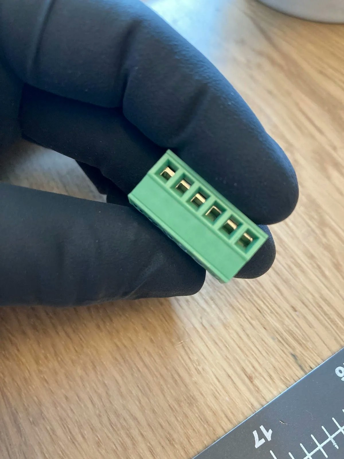
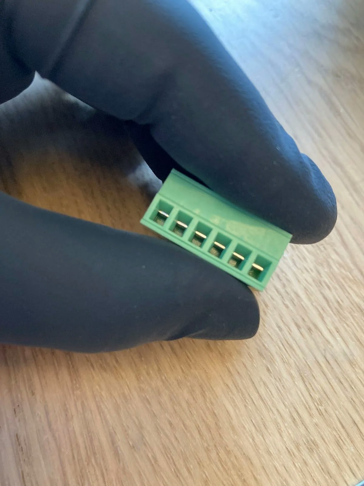
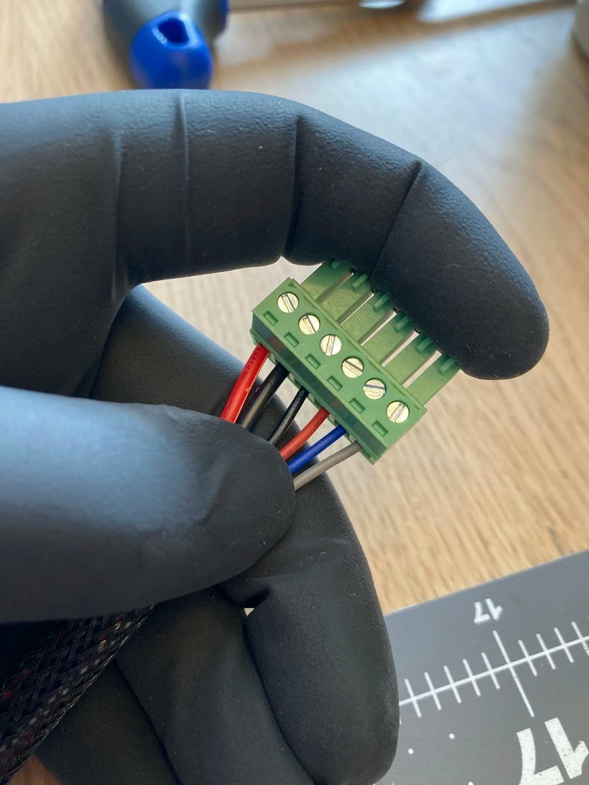
The green connector is a 6-position screw terminal block that accommodates all 6 wires: 2 from the power cable and 4 from the PH04 signal cable. No crimping required—simply insert stripped wires and tighten the screws.
If you have your OSSM remote connected to the board during testing, the device cannot complete homing. This is expected behavior—homing requires your OSSM to be fully assembled with the rail installed.